3D Scene's View Properties
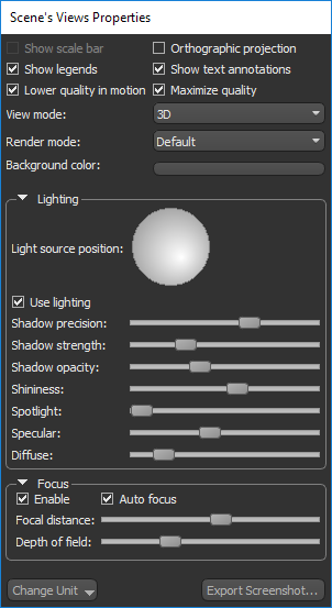
The options in the Scene's Views Properties panel, shown below, let you to select the elements that are shown in a 3D scene view, choose a render mode, modify the background, as well as adjust lighting and other visual effects.
Scene view properties for 3D views
See 2D Scene's Views Properties for information about setting the properties for 2D scene views.
The options in the top section of the Scene's Views Properties panel let you select the elements you want to be visible in the 3D scene view, as well as the render mode and background color.
| Description | |
|---|---|
|
Show scale bar |
If selected, a floating scale bar is shown in the 3D view of the current scene (see Scale Bar for Orthographic Projections). Available for orthographic projections only, |
|
Orthographic projection |
If selected, the 3D scene view will appear in orthographic projection mode instead of perspective projection mode (see Perspective and Orthographic Projection Modes for more information about projection modes). NOTE In the parallel projection of orthographic mode, there is no foreshortening or vanishing point and dimensions can be communicated unambiguously. Although perspective viewpoints can provide more information about depth and often tend to appear more realistic, orthographic viewpoints can make it much easier to compare objects, such as the parts of a molecule, as there is no question about how the viewpoint may affect the perception of distance or size. |
|
Show legends* |
If selected, the legend associated with the currently selected object will be shown in all 2D and 3D views of the current scene (see Legends). |
|
Show text annotations* |
If selected, the text annotations will be shown in all 2D and 3D views of the current scene (see Text Annotations for 3D Views). |
|
Lower quality in motion |
If selected, the level of detail will be diminished during movements. For example, in Track or Pan mode. In general, selecting this option will increase speed during image manipulations. NOTE Selecting this option will not adversely affect exported animated sequences. |
|
Anti-aliasing |
If selected, smoothing of jagged edges on curved lines and diagonals will be applied. |
|
View mode |
The options in the View mode drop-down list allow you to change the View mode, which determines how image data is displayed. Slice… Displays data in the selected view in slices (see 2D Views). Slab… Displays data in the selected view as a slab, in which the maximum, minimum, or average values within a thickness value are shown (see Working in Slab Mode). 3D… Displays data in the selected view in 3D. Note that only one view in a scene layout can contain a 3D view. |
|
Render mode |
The following rendering modes can be selected for 3D views in the submenu. Default… Applies the default rendering mode. MIP (maximum intensity projection)… Displays data using only the highest values for each visible voxel. ISO…Renders surfaces as data points that share the same value.
To edit, enter the isovalue that will be used to generate the surface in the Isovalue edit box that is available in the Data Properties and Settings panel (see 3D Settings). |
|
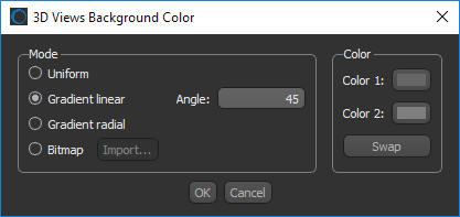
Background color** |
Changes the background color or gradient of the 3D view. You can also use a bitmap as the background.
|
|
Change Unit*** |
Allows you change the default length and angle units displayed for text annotations, legends, measurements, and the dataset properties.
|
|
Export Screenshot |
Allows you to save a screen capture of the contents of the active view — including the scale bar, legends, annotations, regions of interest, and other objects that are visible onscreen — to a number of standard file formats (see Exporting Screenshots). |
* See Selecting the 2D Settings Preferences for information about setting the default preferences for the legends and text annotations.
** See Selecting the Colors Preferences for information about setting a default background color or gradient.
*** See Selecting the Views Preferences for information about setting a default unit for measurements and a default angle unit.
The options in the Lighting box, shown below, allow you to change the direction of the light illuminating objects in a 3D view, apply shadowing effects, and select material properties such as shininess, specular, and diffuse. You should note that many of the lighting options produce the best results when used in combination. For example, shadow precision with shadow depth or shininess with specular.
Lighting properties
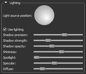
You should note that some lighting controls, such as shadowing and material properties, are not available for orthographic projections.
| Description | |
|---|---|
|
Light source position |
Click anywhere on the Light widget to change the direction of illumination. Changing the direction of illumination can have a dramatic effect when visualizing objects in a 3D view. |
|
Use lighting |
If checked, lighting effects will be applied to the objects in the 3D view. |
|
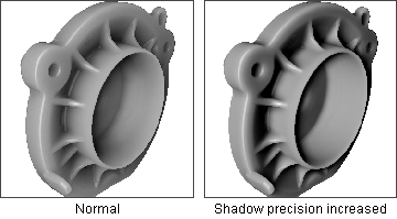
Shadow precision |
Determines the fineness or coarseness of rendered shadows. Increasing the shadow precision with the slider will result in shadows that are more defined or precise.
|
|
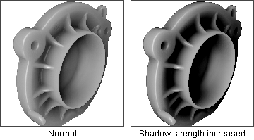
Shadow strength |
Determines the strength or depth of shadows. Increasing the shadow strength with the slider will result in darker shadows.
|
|
Shadow opacity |
Determines the opacity of shadows that are cast on and by objects in 3D views. |
|
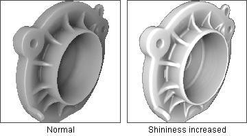
Shininess |
Determines how much smooth surfaces of an object reflect light. Increasing the shininess with the slider will result in surfaces that reflect more light. Usually adjusted in conjunction with Specular and/or Spotlight.
|
|
Spotlight |
Determines the strength of spotlight effects on reflective surfaces. |
|
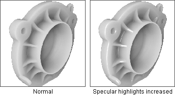
Specular |
Determines the strength of specular reflections originating from the surfaces of an object and is a characteristic of light reflected from shiny surfaces. Increasing the specular lighting with the slider will result in increased reflections.
|
|
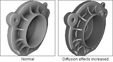
Diffuse |
Determines the strength of diffuse light reflected from the surfaces of an object and is a characteristic of light absorbed by surfaces. Increasing the diffuse lighting with the slider will result in surfaces being more defined.
|
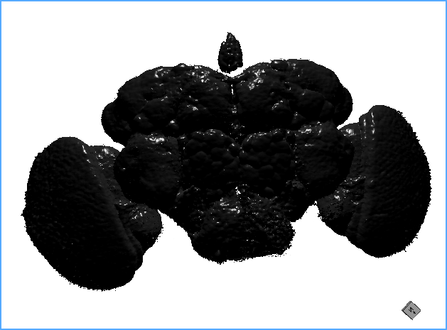
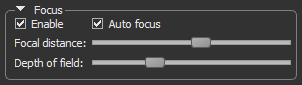
The Focus properties — Focal distance and Depth of field — let you sharply define objects or features of interest in an image while blurring other objects and features. The focal distance and depth of field are calculated from bounding box of the currently selected object.
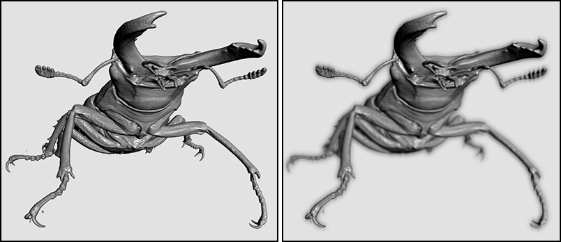
As shown in the example below, all features are sharply in focus in the original image on the left. With focus enabled (image on the right), it is possible to focus in on the beetle's mandible and palps, which can create a more dramatic visual.
| Description | |
|---|---|
|
Enable |
Check this item to enable the focus controls — Focal distance and Depth of field. |
|
Auto focus |
Automatically optimizes the focus of the camera. You should note the focal distance is calculated from the bounding box of the selected dataset and is placed at a depth of one third from the front. |
|
Focal distance |
Allows you to focus in on a particular feature or area of interest.
|
|
Depth of field |
Determines the range of distance in front of and behind a focused object within which other objects will also appear clear and sharply defined in the resulting image.
|